Report on our meeting 03-03-2022, a demonstration by Nick Simpson.
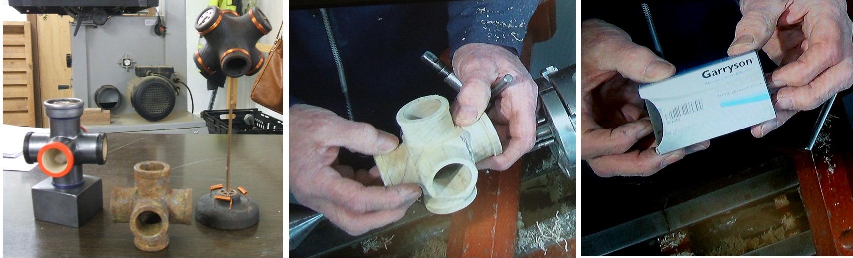
Our meeting this week on Thursday 3rd March 2022 was a demonstration by Nick Simpson. Nick was to make a Tricylinder, this is an example of a joint where multiple pipes intersect, normally made out of metal for the plumbing industry but for our purposes it’s made out of wood. This is an exercise on working out how to make such an item. The time we had available did not allow Nick to make a complete Tricylinder at his demonstration so he had prepared several at various stages, these he then explained how he got there. He did go on to do some of the more challenging parts of his Tricylinder including explaining the process that was needed to achieve his goal.
Nick also went on to explain some of the “Tips” programme he had introduced during the close down, there had been a good response from the members for the “Tips” throughout the whole of the close down and he shared a few of them at this meeting.
I have presented Nick’s demonstration as a form of timeline, taking you through the thinking process as well as the practical process of actually making a “Tricylinder” what follows are a series of pictures with some text to help you understand exactly how Nick made the “Tricylinder”.
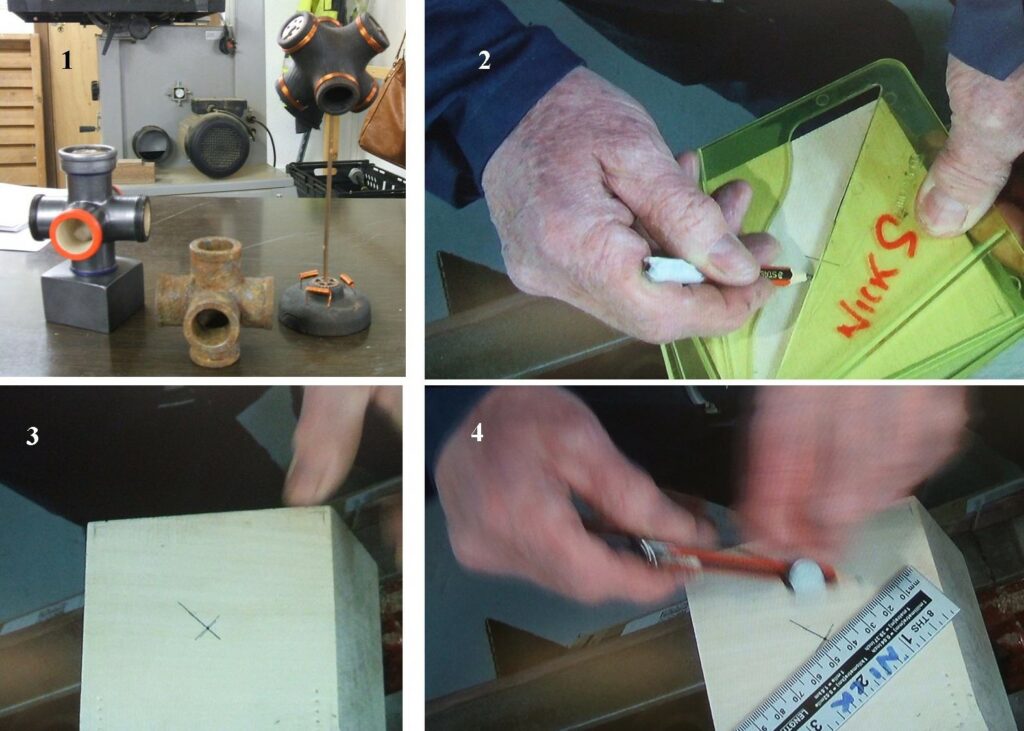
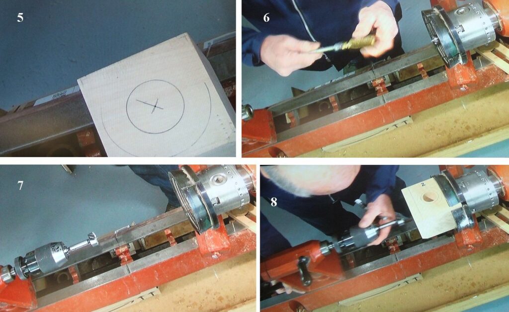
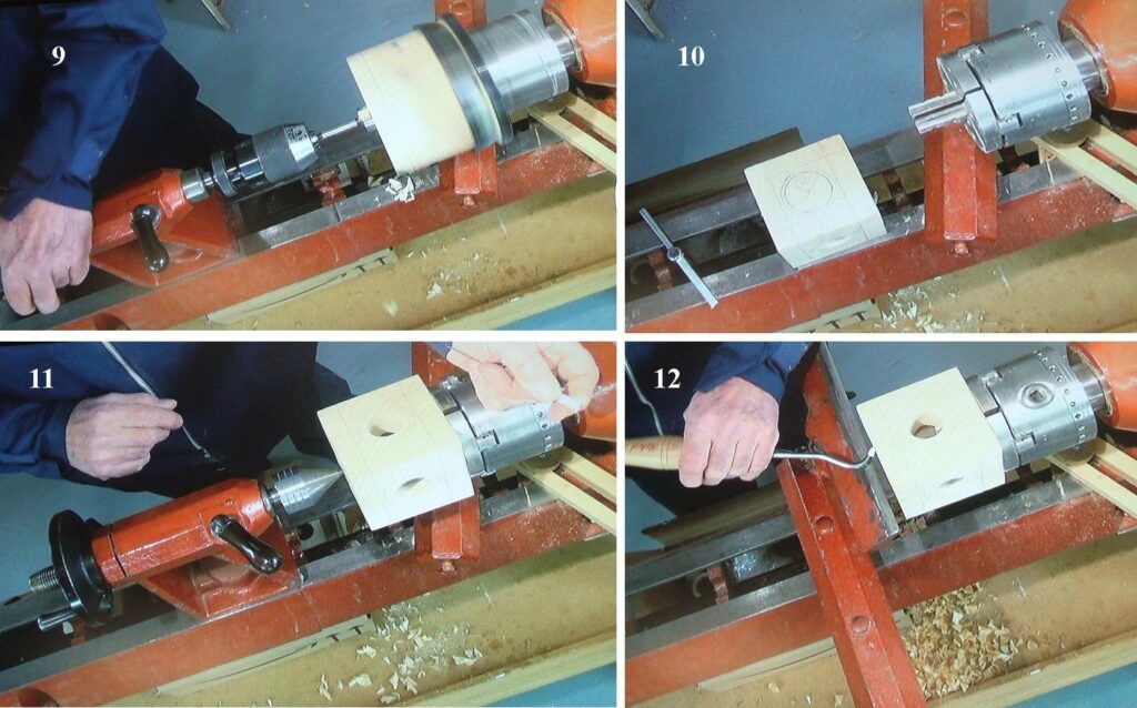
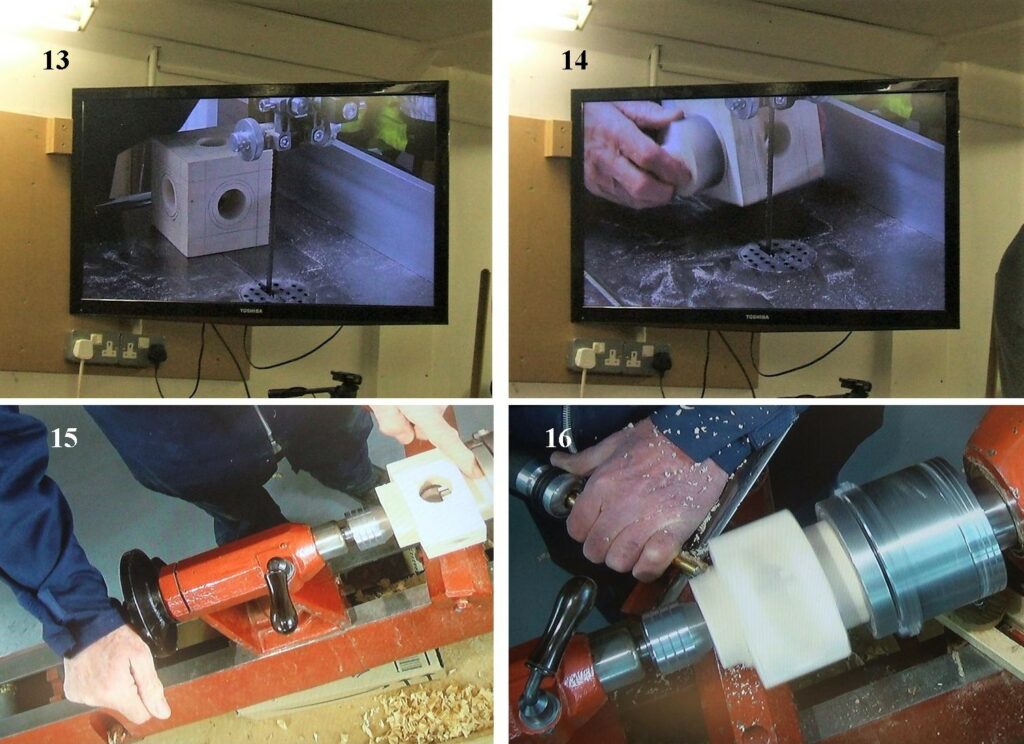
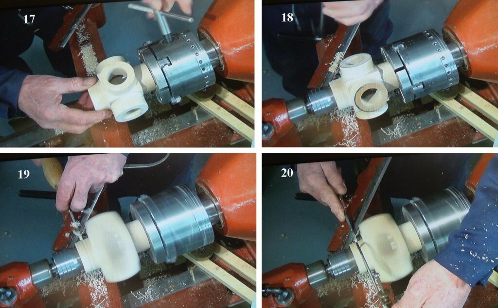
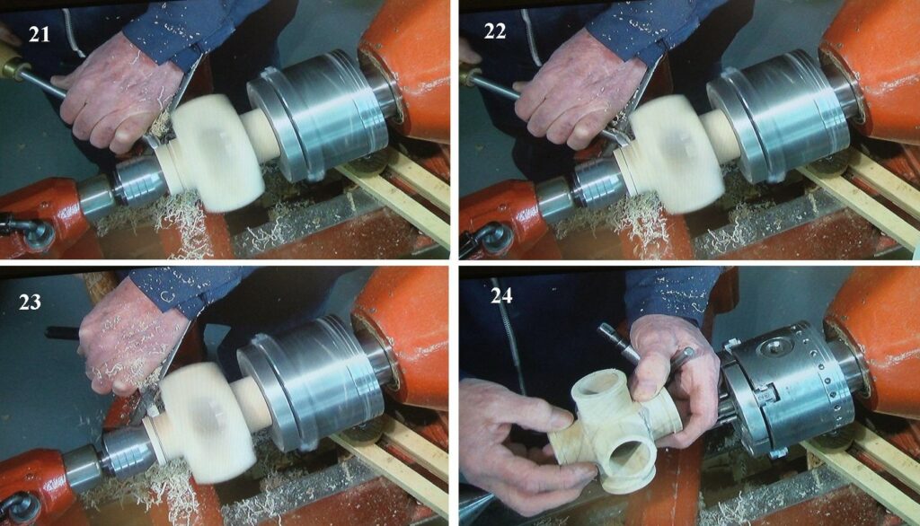
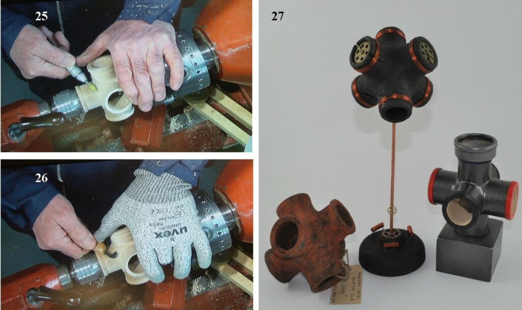
1, Here are 3 Tricylinders that Nick had made, he put them on display as he started his introduction, explaining some of the differences in each of the 3 examples. 2, Nick started by marking out the middle of one of the faces in his blank, Nick explained that the blank used needed to be as near a perfect square as possible. 3, The middle of one face now marked, all 6 faces needed to be marked similarly. 4, Now Nick makes a circle to suit the size of the drill used, this would also double as his holding method with a pin chuck at a later stage,5, the inner circle would be the size of the hole to be drilled. 6, Before Nick mounted the drill chuck in the tailstock, he took the time to show the members how to keep the taper in the tailstock quill clean, he used a brass brush that was more commonly used to maintain a shot gun. 7, the drill in the morse taper chuck and now mounted in the tailstock, Nick also used a large set of jaws in the headstock chuck to be able to hold the square blank. 8, the drilling begins, each of the 6 faces needed to be drilled to just over half the depth with this method, do not go all the way through at this point.9, the last of the 6 holes now being drilled to just over half the depth, keep the speed low for the drilling and give the drill time to work, no more than 400rpm. 10, now Nick mounted the pin jaws in the chuck, all 6 faces would now be drilled using the holes already drilled to complete the through holes, be aware not to drill too far as you could come in contact with the pin jaws. 11, with all the holes drilled it was time to clean up the inside of the holes from any splinters left from the drilling process. 12, Nick used a hook tool to clean up the internal edges of the holes, be aware this method does have some risks and takes practice to perfect, may be better to just use a strip of coarse sanding medium.13, some of the waste wood can be removed with the use of a bandsaw, mark out where the cuts should be and carefully cut with the bandsaw, all 6 sides need to be treated in the same way. 14, Nick showed a home made device for holding the blank while band sawing, a turned piece of wood that fitted into one of the holes, keeping your fingers out of the way whilst cutting. 15, you will end up with the blank having all 6 sides cut down ready to mount on the lathe, here you can see the blank back on the pin jaws and the tailstock taken up to give support. 16, Nick starts to round over the 1st of the 6 sides, they need to be done one at a time and only the part nearest the tailstock taper gets worked, this is then repeated on all 6 sides.17, the initial rounding over now complete, now it’s time to make the final shaping. 18, Nick positions the tool rest to work the next part, do turn the work piece by hand after positioning the tool rest just to make sure the other projections don’t come in contact with the tool rest when spinning. 19, Nick then used a parting tool to bring the turned areas down to his desired size. 20, here Nick can be seen using a set of callipers to determine the size as he cuts with the parting tool.21, bringing the work piece down to the correct size, a fingernail ground tool would be the best choice. 22, continuing to trim to size, all 6 sides need to be done the same. 23, now forming the final shape, Nick would leave a short flange on all 6 sides, the tool of preference for this was a type of Bedan, much like a parting tool only wider and ground with a convex bevel. 24, this is what you will end up with after the turning has been completed, now the parts that could not be worked on the lathe need to be completed by hand.25, there will be areas at each intersection that need to be removed by hand, here Nick is using a flexible drive with a grinding stone to remove the waste. 26, as an alternative a hook tool used for carving could be used, followed by some fine sanding. 27, 3 examples of “Tricylinders” that Nick had made, left, this one was painted to look like it was rusting, centre, this one was scorched and some copper wire used to give some contrast, right, this one was smooth painted and one end threaded.
That concludes the demo as far as the “Tricylinders” is concerned, I do hope you were able to follow the timeline and that you might have a go at making one yourself. Nick went on to talk about the “Tips” programme that was introduced during the close down, here are 3 of the items Nick talked about.
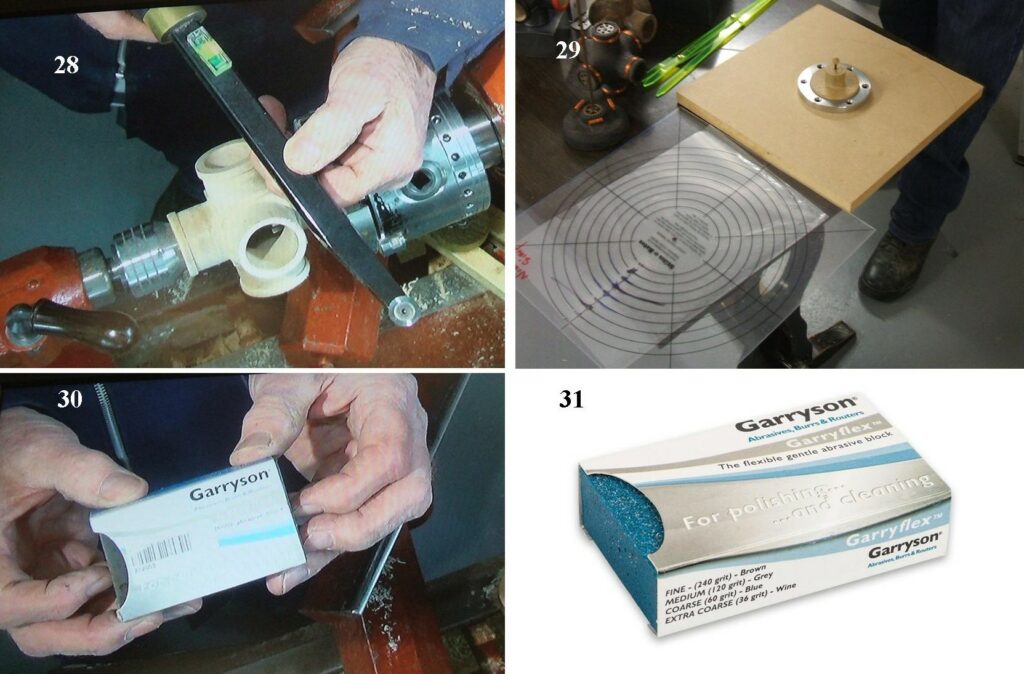
28, Nick showed the members this Carbide tool and explained how it should be used, he stressed the point that it should always be used with the handle higher than at the cutting point, the cutting point should also, be as near to centre level as possible, failure to do this could risk the tool creating a catch. 29, Nick showed some of the methods he used for centring a faceplate ring using a piece of wood as a jig that fitted the internal of the faceplate ring, this would have a hole through it to take a thin pin, a corresponding small hole would be drilled in the mounting plate or the face of a bowl blank, the jig would then be located using the pin and the ring slipped over the jig ready to be screwed down. 30 & 31, a useful cleaning and polishing block for use on the lathe bed or tool rests keeping them clear of any contaminants, comes in 4 grades the one Nick had was a medium grit of 120.
That ended Nick Simpson’s presentation, he then received a round of appreciation from all the members present, this was Nick’s first demonstration to our club, he was assured that it would not be his last.
Our next meeting is on the 17th March 2022, I will be the demonstrator, it’s my intention to make one of Mick O’Donnell’s birds.
This website uses cookies to improve your experience. We'll assume you're ok with this, but you can opt-out if you wish.AcceptRead More
Privacy & Cookies Policy
Privacy Overview
This website uses cookies to improve your experience while you navigate through the website. Out of these, the cookies that are categorized as necessary are stored on your browser as they are essential for the working of basic functionalities of the website. We also use third-party cookies that help us analyze and understand how you use this website. These cookies will be stored in your browser only with your consent. You also have the option to opt-out of these cookies. But opting out of some of these cookies may affect your browsing experience.
Necessary cookies are absolutely essential for the website to function properly. This category only includes cookies that ensures basic functionalities and security features of the website. These cookies do not store any personal information.
Any cookies that may not be particularly necessary for the website to function and is used specifically to collect user personal data via analytics, ads, other embedded contents are termed as non-necessary cookies. It is mandatory to procure user consent prior to running these cookies on your website.