Our meeting on the 18th February 2021 was to be all about dealing with snags and finding solutions to those snags, it was being handled by John Ruickbie but due to the ongoing Covid-19 restrictions it had to be turned into a virtual meeting. You were all invited to put something forward for this meeting, John did put in a very comprehensive report on a spinning wheel he worked on that threw up some problems he had to find solutions for. In addition to John’s report, Geoff Potter put in a suggestion rather than a snag that I thought warranted publication. I have also put forward something along the same lines as Geoff, Dave Line also put in a presentation for the solution of needing a drum sander, but we will start with John Ruickbie’s presentation,
Making a model spinning wheel
Most of my work now involves working with several pieces of wood and other materials such as metal or plastic. The work requires extensive research and design this is about my efforts at making a spinning wheel.
An old family friend made one in the 19 60s and I had it in a bag but it was broken beyond repair I think even for the repair shop. I was intrigued about how the section called the mother of all ran at two speeds driven from one drive wheel. The twist of the wool depends on the flyer running at a different speed from the bobbin. On line I was able to research this and discovered the two items had different sized pulleys driven by a continuous double loop drive band. The drive wheel was the first part I turned and soon got into difficulties. The holes in the rim for the spokes could not be drilled in a completed wheel as they do not go through and must be drilled from the inside so I resolved this by turning it in four sections with newspaper joints. For those who have not used this technique it involves spreading glue on the joint and rubbing the surfaces together to get an even spread on each face then parting and clamping with a single layer of newspaper in the joint allowing the joint to be parted with a knife later on. Care has to be taken when turning to avoid stressing the joint .l kept the sections deeper than required and turned the outer rim first and secured it with a cable tie before finishing the inner rim .This method allowed me to mark the required holes before opening the joints. Please remember to mark the sections for reassembly Care has to be taken to avoid a hole in a joint pre planning is required to avoid this by altering the number of spokes or wheel segments. I do have another solution to this problem but it takes a lot of explaining so will leave it for another time. The hub is straight forward and can be drilled using the lathe indexing and a drilling guide which can be made from a block of wood fitted in place of the tool rest. Purpose made ones can be purchased but a temporary wood one will with care probably do one wheel. The spokes need to be identical and can be turned using a template. It is important to have the length accurate as the hub centre depends on this.
Assembling the wheel is best done with a jig I use a MDF jig with a central rod for the hub and the hub and rim dimensions carefully turned. A dry run is essential before gluing. Clean up the newspaper faces then do a complete glue up in one go. Keep the joints clean of excess glue and clamp with a cable tie.
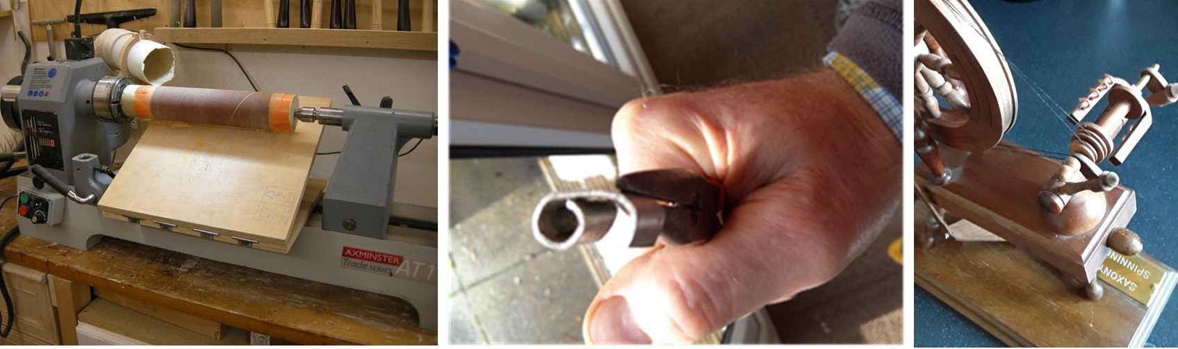
A problem arose with this method of assembly . The wheel had glue joints which needed sanded and two decorative lines were required on the sides of the wheel. I overcame this problem by making a jamb chuck to hold the wheel and finished each side using the rotating centre in the hub. The jamb chuck must have the centre at the correct depth to support the hub otherwise the pressure from the centre will cause it to distort. The inner surface was finished before assembly requiring light hand finishing at the joints. The outer surface of the wheel requires a raised lip on each side allowing the drive cord to run in the centre. I found this fitted on the Cole jaws allowing the buttons to be fitted between the spokes using minimum pressure and light cuts. I also cut a circle of thin ply to go between the jaws and the rim to avoid striking the jaw sections. The rim faces could have been done this way but I was concerned that it would have been easy to strike the buttons when turning. The section called the mother of all consorts of a hollow shaft with a free running bobbin on it with the larger pulley attached to the bobbin. The flyer is a u shaped section attached to the shaft with the smaller pulley allowing it to spin faster than the bobbin. On full size working wheels the pulleys can be changed to alter the twist of the yarn. This assembly is attached to two vertical posts called maidens mounted on a horizontal shaft. Those parts are turned with a design complementing the spokes and finishing in heads to accept the shaft and the shaft drilled to accept the maidens. This assembly moves to allow the drive cord to be tensioned . I used a small hollow brass rod from the local DIY store for the shaft. Another problem solved. The assembly is mounted on a turned block with a Tenon in a slot in the base which I drilled and cut a half inch thread in it this is controlled by means of a half inch wooden screwed rod with a knob attached. When I made this I discovered my old threading tool was damaged so I had to buy a new set and remake the parts. Another problem was that the mahogany wood did not take a good thread but I had a very old piece which was ok with very careful cutting and plenty of linseed oil. The threads are hidden so I did not worry about the oil on the wood. The tenon which runs in the tensioning slot did take a good thread.
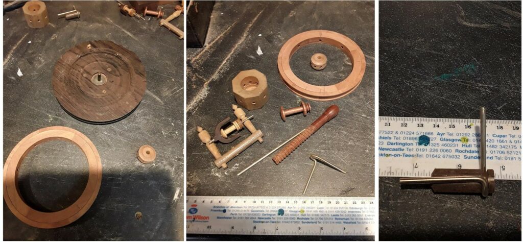
I use a small lathe for turning smaller parts using pen turning tools and a small skew chisel allowing me to get finer detail. The flyer was cut on the scroll saw and hand finished it is glued to the shaft which runs through the bobbin allowing the bobbin to run independently with the shaft whorl (pulley) glued at the far end. On a full working wheel this could be removed to allow the bobbin to be changed. The bobbin has a fixed whorl which could be changed on a full working model. The assembly of this section can be seen in the close up picture. The hooks on the flyer are just small sections of copper wire and would be used to guide the yarn on to the bobbin. This is how the flyer and bobbin can run at different speeds
I have also included a picture of some of the parts of the old spinning wheel along with my first failed threaded shaft.
The base and legs are just an oblong block with three legs the legs designed in sympathy with the other components. The base is at an angle requiring the holes for the legs to be drilled at the correct angles I made a drawing of this to ensure both the angle and the length were correct. The drawing can be full scale and does not need to be detailed. I guessed the base angle as i could find no reference as to what was correct I made it 80 degrees from vertical with the single leg at 90 and the two shorter legs at 60 to the base block.
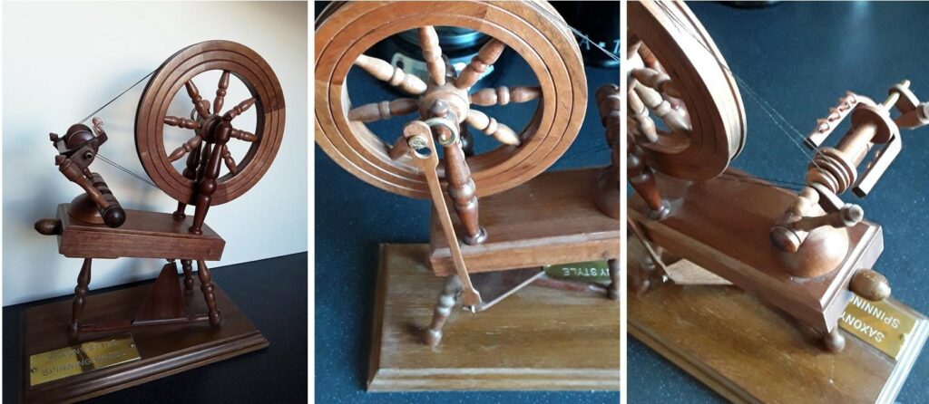
One problem was the single long leg was under the tensioning device which I overcame by fitting a block under the main block requiring the leg to be shortened. The drive wheel is driven by a treadle mounted between two of the legs with a crank fitted through the boss of the wheel . The treadle is connected to the crank by a strip of wood tied to the treadle and clipped to the crank by means of a keyhole slot in the wood strip.
This assembly is shown in a picture of the back of the wheel showing the crank arrangement. The crank was made from solid brass rod 3mm diamond which was bent on a jig which is shown in one of the pictures. I had to have this made as my metal lathe skills are zero.
Once assembled I used builders twine as the drive cord which was tricky to do but when I managed to make it work it made all the effort worthwhile.
I went through the same procedure when making the model of Mons Meg but had accurate drawings to work from. This may seem a lot of effort but it is a hobby and being able to achieve something that is accurate or works make it worth the effort. The latest project is a model Viking ship for my grandson.
Regards, John Ruickbie.
I have to thank John for his comprehensive report on the spinning wheel, along with this presentation John told me that he was no writer, I have to say I beg to differ. Thanks John.
Now we have something from Geoff Potter, this is not a snag but it could be classed as a solution. He has come up with a form of branding to mark your work pieces.
HINTS AND TIPS – BRANDING
If your piece of woodturning is good then I think it’s a great idea to sign or mark your work.
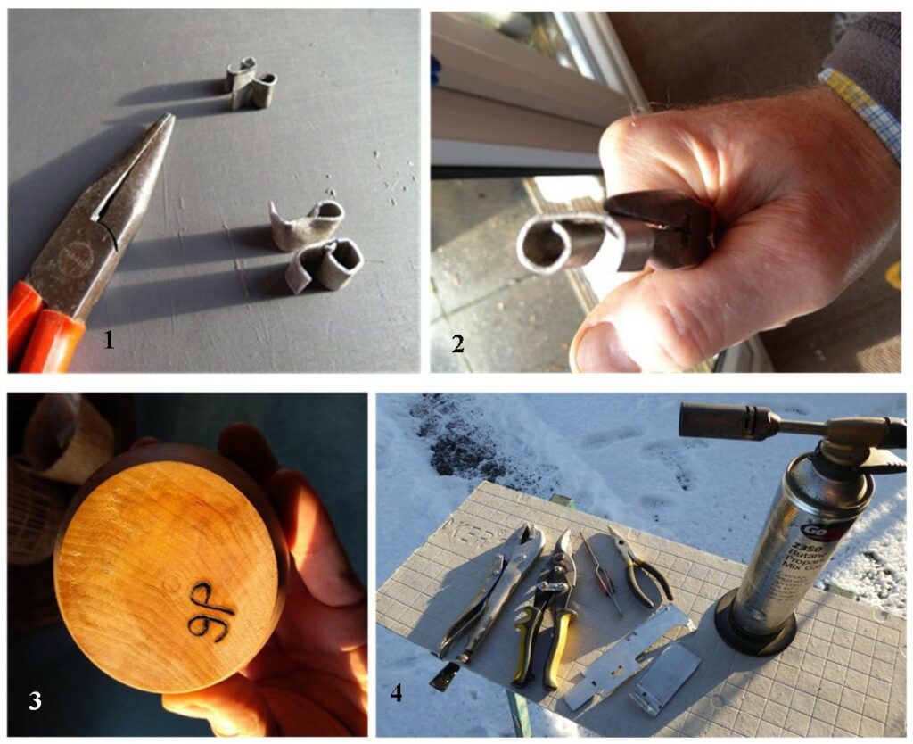
1, I have a quick easy method of doing that and it may be done on the finished or part- finished item.
I have bent small pieces of plate metal to form letters of my initials.
2, You simply hold the letter end wise on in a pair of pliers or tongs, heat the letter to red hot then brand the turning, usually on the base. It leaves an indelible mark. I have made two sizes of letters to suit different sized turnings. The mark shows up well against even dark wood. The beauty is that the mark is also repeatable.
repeatable.
3, By using bent plate – the letter holds more heat and the letter is more rigid.
Anyone who has welding or rivetting skills could form the two letters into one object. The shape is not confined to initials – you could use any design of mark.
Keep it simple.
This is the end result of my efforts.
4, To use this method you will need some of this equipment and material.
Scrap Metal any thin scrap metal will do. It is easiest to use aluminium if you can as it is easier to cut and shape. Beware of overheating the aluminium though when you are branding.
Cutters and pliers for shaping the metal. A vice, saw and files are handy. The branding face of the metal letter needs to be flat so that you get an even mark.
Mole grips or spring loaded tongs – these have a better positive grip than pliers for holding the hot metal letters when you are branding.
Blowlamp – mine has a clipped-on broad base to keep it stable on the work surface whilst you are heating the letters.
Heat proof board or metal sheet to protect your bench from the hot metal and blowlamp.
Because of the danger from flames, hot metal and some slight fumes it is best to do your branding outdoors on a workbench or on the ground. Snow covered ground is optional! If you do it indoors then use ventilation and make sure that you protect your work surface and keep clear of absolutely anything flammable. Or do it on the concrete floor if you have one.
Do not do the branding anywhere near your lathe! Wood dust and shavings are highly flammable and can actually be explosive.
It may seem obvious but I would recommend you use sturdy gloves and have a fire extinguisher to hand, certainly if you are indoors. Don’t leave the lit blowlamp unattended.
Of course some Highland Woodturners’ Club members will have pyrography equipment and could do the same thing but perhaps freehand each time. I know also that there are a very few members who can use their laser cutting/burning printer.
It is probably also a good idea to add information about the type of wood and maybe the source of the wood to the base of your woodturned article too. It all adds interest.
Using an ink marker successfully depends on the type of wood and the drawback of possible bleeding of the ink. A good old pencil is a good choice. Pencil does not fade and does not bleed. I would suggest a fairly soft pencil as if it is too hard it will leave a dent and make a fainter mark.
You may need to rest your wrist on a box or block so that you can write accurately.
The use of latin names may add a certain kudos. Acer Psuedoplantanus sounds better and more mysterious than sycamore?
It is probably best to apply any writing before applying finishes, so that the finish also protects the writing. Be careful not to blur the writing! Always practice everything on a spare piece of wood.
A simpler but less permanent way to mark your turning is to simply stick a paper label underneath!
GEOFF POTTER
Now we have something from Dave Line, Dave solved the problem of not wanting to spend a lot of money on a drum sander, here is Dave’s solution, and this is what Dave had to say about his solution.
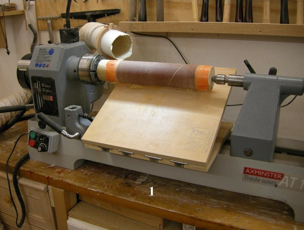
Hi Alec, I thought I would show the drum sander I have made for my Lathe (since I can’t afford a sanding thicknesser).
I use it mainly to get my segmented rings dead flat and of uniform thickness when segmenting turning ready for gluing. It is also useful for sanding almost anything flat I.E. sacrificial chuck mounts for bowls.
The drum is 400mm long and 75mm diameter, I find a speed of about 1000rpm works best.
The first picture shows the sander mounted on the lathe ready for use.
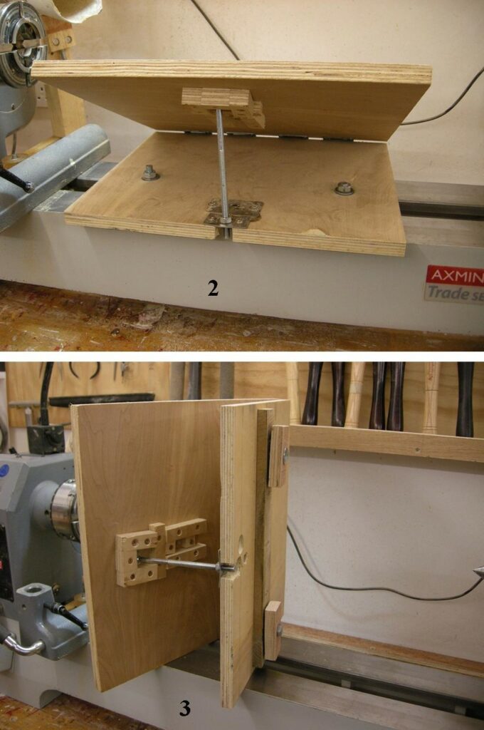
The second picture shows the bolt at the back for altering the thickness.
The third picture shows the base and how it is attached to the lathe bed using the two blocks under the bed and tightened.
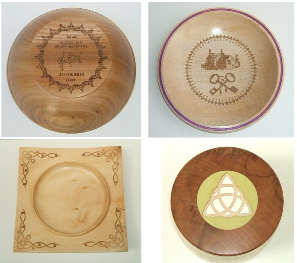
As the last entry for this post it comes from myself and as I mentioned earlier it’s something along the same lines as Geoff has suggested only this piece of equipment came with quite a high price tag, I have a Laser Engraver Cutter.
Our next meeting is due on the 4th March it too is being organised by John Ruickbie, John’s theme for that meeting will be making goblets, this will also be a virtual meeting and you are all invited to make and share your goblet with us.
Do remember the Clubhouse remains closed.